
WEEK 9 OUTPUT DEVICES
Individual assignment
Add an output device to the microcontroller board we have designed and program it to do something
Group assignments
Measure the power consumption of an output device
Find the link to the group assignment here
Since it happens to be an electronics week, as always I started with almost zero idea as to what to do. I still had doubts regarding my final project idea. And for now I fixed it to a plastic shredder (god knows how long that’ll be the case). And so I was suggested to try stepper motor as the output device.
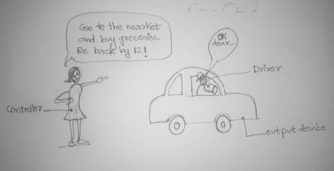
So according to my very smart friends in fablab who know a lot about electronics. In order to run an output device you need a microcontoller and a driver. The contoller gives directions to the driver and the driver makes the device do that. The driver does’nt take any decisions of its own. But the driver requires more power than the contoller though. the power that’ll be needed to run the output device.
1.Choosing the output device
Outputdevice: Stepper motor Nema17
Controller: Atiny 1614
Driver: DRV8825
NEMA 17
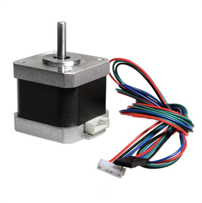
Features of NEMA 17 Stepper Motor
- 2 phase motor with bipolar configuration
- Requires a driver that can reverse the current direction to achieve motion.
- It has a step angle of 1.8 degrees, which translates to 200 steps per full revolution contributing to precise control of movements
- The holding torque varies from 12 N.cm to over 50 N.cm. Holding torque is a critical factor since it determines the maximum load the motor can handle without losing position when stationary.
NEMA 17 is a standard size for stepper motors. The "NEMA" part stands for the National Electrical Manufacturers Association, which sets standards for various electrical products. The number "17" refers to the faceplate size of the motor, which is 1.7 inches (approximately 42.3 mm) square. NEMA 17 motors are widely used in 3D printers, CNC machines, and other applications requiring precise control of motion.
Types of Stepper Motors
There are several types of stepper motors, but the most common types are:
-
Unipolar Stepper Motors
:
- Have six or eight wires.
- Use a center-tapped winding, which allows for simpler driving circuits.
- Typically easier to drive but less efficient and less torque compared to bipolar motors.
-
Bipolar Stepper Motors
:
- Have four wires.
- No center tap; each winding must be driven in both directions.
- Require a more complex driving circuit but are more efficient and provide greater torque.
Microstepping
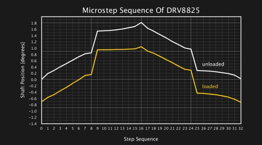
Microstepping is a technique used to increase the resolution of stepper motors by dividing each full step into smaller steps. This is achieved by varying the current through the motor windings in a controlled manner. Common microstepping settings include:
- Full step
- Half step
- Quarter step
- Eighth step
- Sixteenth step
- Thirty-second step
Microstepping improves the smoothness of motion and reduces vibrations, which is particularly important in applications requiring precise control.
Configuration of Motor Driver
A motor driver controls the current flowing to the stepper motor's windings, determining its movement. Popular drivers for NEMA 17 stepper motors include the A4988 and DRV8825. Here are the typical configurations:
-
DRV8825 Stepper Motor Driver
:
- Power Supply : Typically operates between 8.2V and 45V.
- Current Limiting : Adjusts the maximum current with a potentiometer.
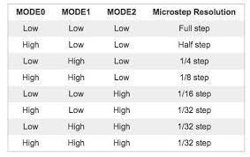
- Microstepping : Supports full step, half step, quarter step, eighth step, sixteenth step, and thirty-second step.
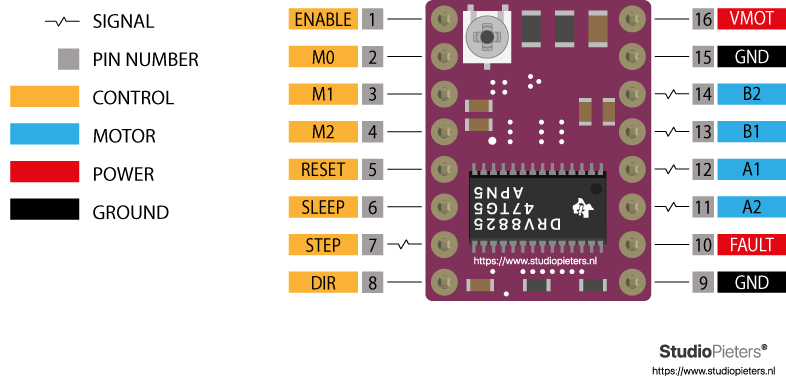
-
Pin Configuration
:
- VMOT and GND for power.
- 2B, 2A, 1A, and 1B for connecting to the motor.
- Step and Dir pins for step and direction signals.
- Enable, M0, M1, and M2 for enabling the driver and setting microstepping.
Setting Up the Motor Driver
To set up a motor driver with a NEMA 17 stepper motor:
- Connect Power : Connect the VMOT and GND pins of the driver to an appropriate power supply.
- Connect the Motor : Connect the motor wires to the driver's output pins (2B, 2A, 1A, and 1B).
- Configure Microstepping : Set the microstepping mode using the MS1, MS2, and MS3 (A4988) or M0, M1, and M2 (DRV8825) pins.
- Adjust Current Limit : Use a small screwdriver to adjust the potentiometer on the driver to set the appropriate current limit for your motor.
- Connect Control Signals : Connect the Step and Dir pins to your control board (e.g., an Arduino, ESP32). These pins will receive the step and direction signals to control the motor.
Example Code for Controlling a Stepper Motor
Here's a simple example using an Arduino to control a NEMA 17 stepper motor with an A4988 driver:
cppCopy code
const int stepPin = 3;
const int dirPin = 4;

void setup() {
  pinMode(stepPin, OUTPUT);
  pinMode(dirPin, OUTPUT);

  // Set the direction
  digitalWrite(dirPin, HIGH); // HIGH for clockwise, LOW for counterclockwise
}

void loop() {
  // Generate steps
  digitalWrite(stepPin, HIGH);
  delayMicroseconds(800); // Adjust for speed control
  digitalWrite(stepPin, LOW);
  delayMicroseconds(800);
}
This code will rotate the stepper motor in one direction. Adjust the
delayMicroseconds
values to change the speed of the motor. For more complex motion control, consider using libraries such as the AccelStepper library for Arduino.
DRV8825 stepper motor driver
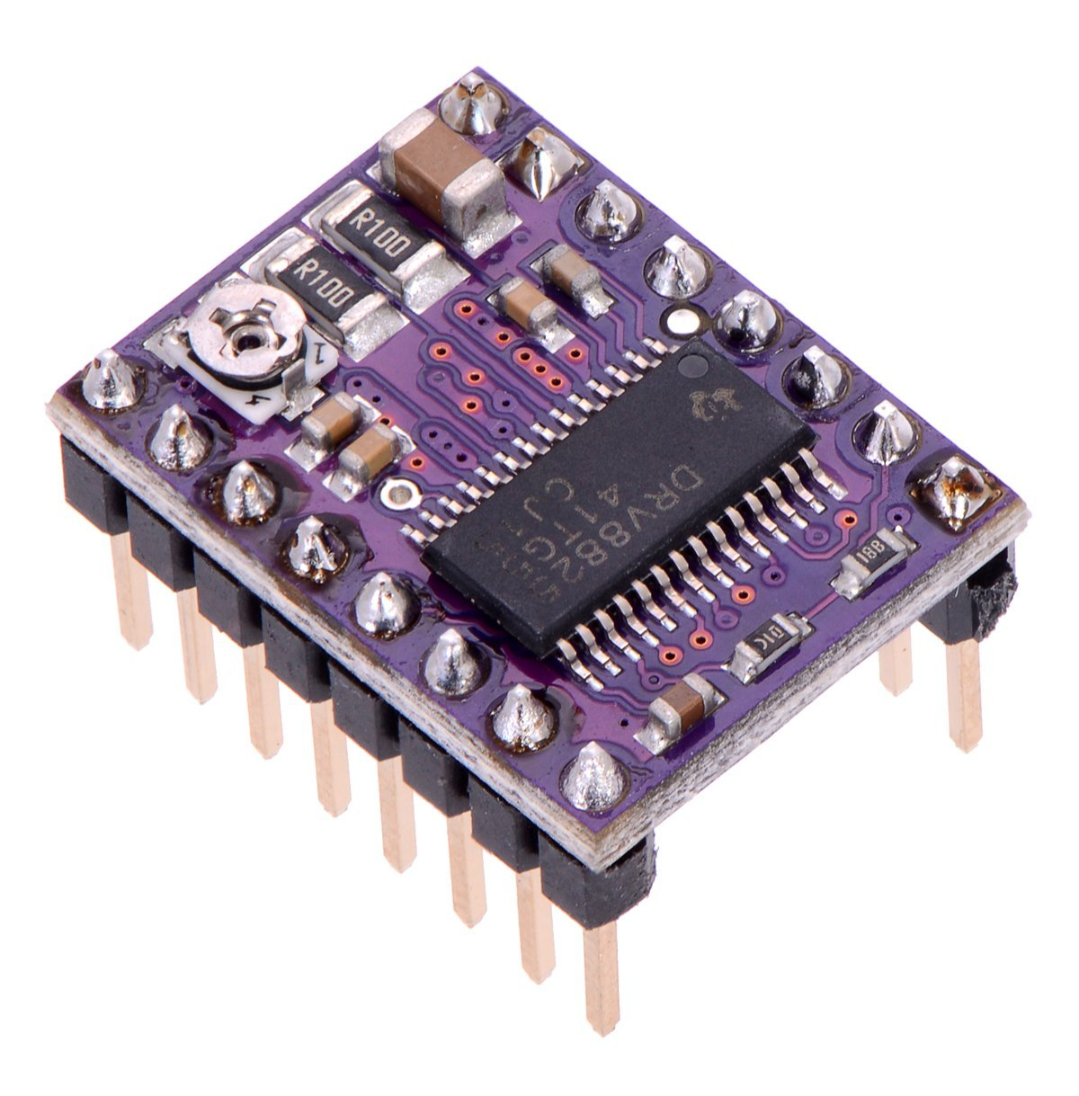
The motor driver can provide higher output power, more accurate output current voltage, frequency control, more precise position control, and higher efficiency.
DRV8825 is a popular choice for controlling NEMA 17 because of the following reasons:
- It can handle motor supply voltages up to 45V and can deliver up to approximately 1.5A per phase. This range is suitable for NEMA 17.
- It supports adjustable current limiting and offers up to 1/32-step microstepping. Microstepping allows for smoother motor motion, higher step resolution, and reduced mechanical resonance, which are crucial for applications that demand precise motion control and low vibration.
- Includes features like thermal shutdown, under-voltage lockout, and crossover-current protection.
- It offers improved performance compared to some other drivers, such as the A4988, in terms of driving capability and heat dissipation.
ATtiny1614 Microcontroller
I used ATtiny microcontroller for this PCB
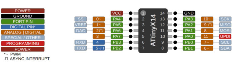
Features
- Utilizes the high-performance, low-power AVR RISC architecture.
- 16 KB of flash memory.
- Supports up to 20 MHz clock speed, providing a good balance between processing power and power consumption.
- Provides support for I2C, SPI, and UART communication, enabling the microcontroller to connect with a wide range of sensors, actuators, and other microcontrollers or microcomputers.
- Includes high-resolution timers and multiple PWM channels for precise control over timing and output modulation, suitable for tasks ranging from simple time-keeping to complex motor control.
- ATtiny1614 can be programmed via UPDI (Unified Program and Debug Interface), simplifying the development process with only a single wire for programming and debugging.
2.PCB designing
A few others were also doing the same so it was easy to follow. I started late so I was also able to omit a lot of mistakes since they already figured it out. For instance, I completed my PCB design suprisingly fast (atleast to me).
Designing the PCB in kicad
Creating the schematic diagram using the above-mentioned components
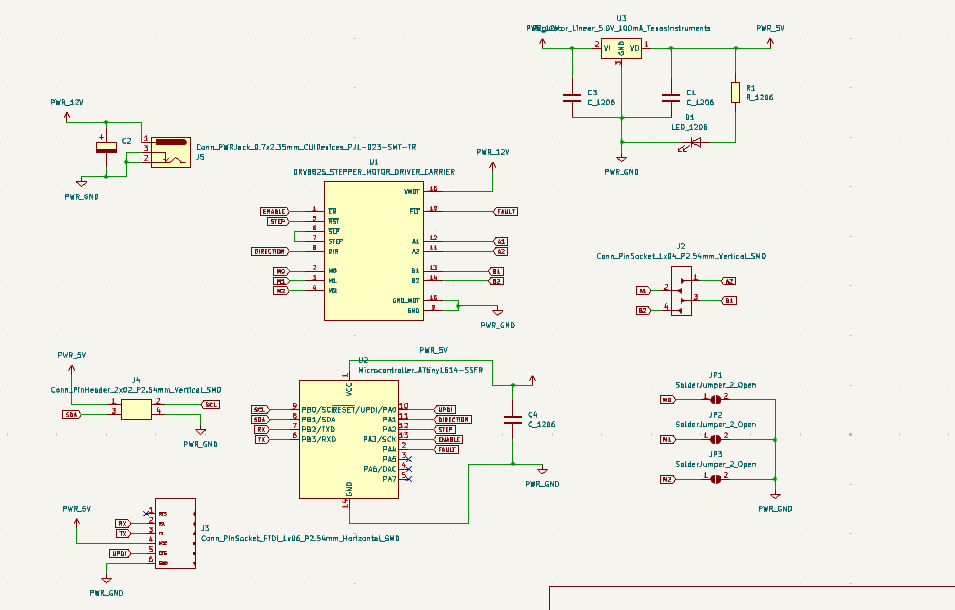
Had to add the footprint seperately of the driver since it was not there
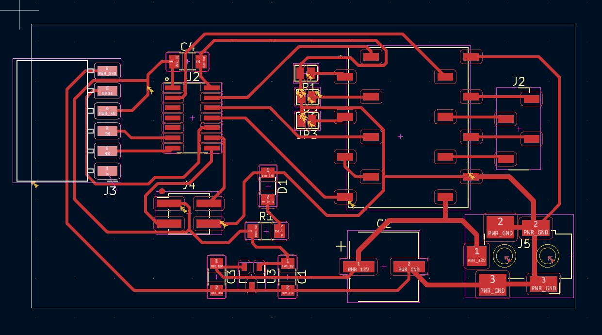
This is the Final PCB design that I have created and it was approved by our instructor
And for Milling this PCB I have Converted the Gerber file to png using Gerber viewer , you can checkout more details of conversion in that link
3.Milling
- The png that I got from gerber viewer was imported to fabmods
- I milled this PCB using our modella PCB milling machine
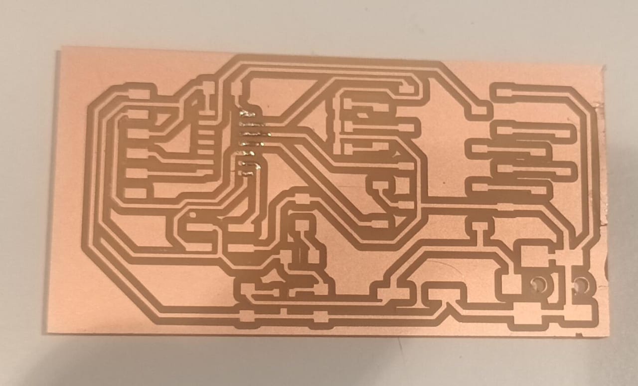
An this was the output that I got, it was pretty neat
Requested components on Fab inventory
.jpeg)
4.Soldering
After collecting the components, I soldered them
.jpeg)
Now my PCB is ready for programming
5.Programming
Install the board manager
Before running the code I had to install the board manager. “ http://drazzy.com/package_drazzy.com_index.json” This is the link I used
File> tool> burn bootloader
.png)
I took an example code from here
// defines pins
#define stepPin 9
#define dirPin 8
#define enablepin 10
#define faultpin 0

void setup() {
  // Sets the two pins as Outputs
  pinMode(stepPin,OUTPUT);
  pinMode(dirPin,OUTPUT);
   pinMode(enablepin,OUTPUT);
  pinMode(faultpin,OUTPUT);
}
void loop() {
  digitalWrite(dirPin,HIGH); // Enables the motor to move in a particular direction
   digitalWrite(faultpin,HIGH);
   digitalWrite(enablepin,LOW);
  // Makes 200 pulses for making one full cycle rotation
  for(int x = 0; x < 800; x++) {
    digitalWrite(stepPin,HIGH);
    delayMicroseconds(700);    // by changing this time delay between the steps we can change the rotation speed
    digitalWrite(stepPin,LOW);
    delayMicroseconds(700);
  }
  delay(1000); // One second delay

  digitalWrite(dirPin,LOW); //Changes the rotations direction
  // Makes 200 pulses for making one full cycle rotation
  for(int x = 0; x < 1600; x++) {
    digitalWrite(stepPin,HIGH);
    delayMicroseconds(500);
    digitalWrite(stepPin,LOW);
    delayMicroseconds(500);
  }
  delay(1000);
}
6.Final result
Connected the board to bench power supply at our lab and made sure the circuit is proper
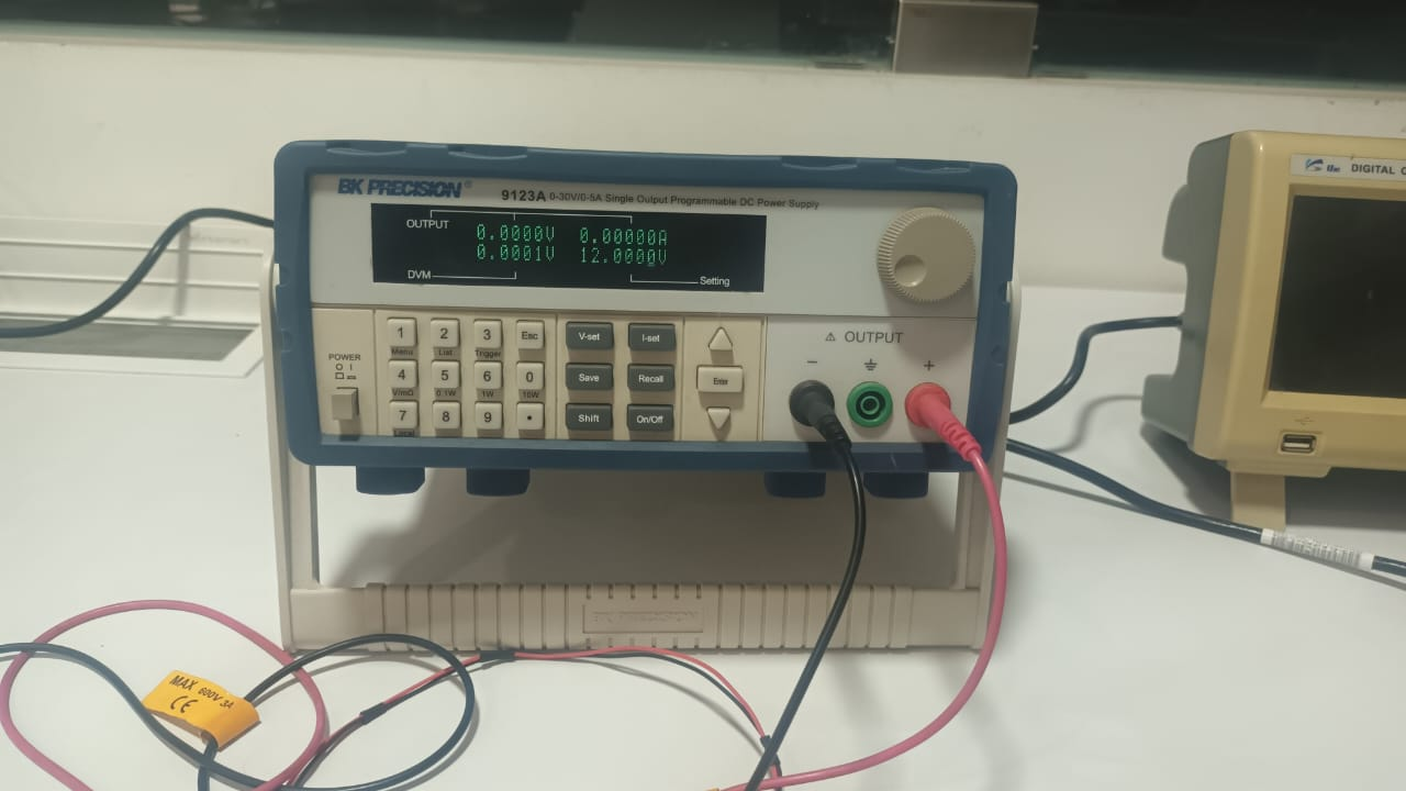
- Here we can see stepper rotating as per the inputs that I have given
Things I learnt this week
- Refer to datasheet of a device before using it
- In PCB design, arranging the components properly saves you lot of time in routing
- Always check the track constraints are defined before you start routing
- Double check labels in the schematic diagram
Download Design Files